
1. Gross Vehicle Weight
Determine the Gross Vehicle Weight, or GVW, by calculating the weight of the empty trailer plus the weight of the intended cargo. For example, a 2,000 lb empty trailer carrying 8,000 lb of cargo has a 10,000 lb GVW.
Axle Assemblies
Use this guide to understand torsion and leaf spring axle assemblies, identify important measurement points, choose the right axle type, and decode common axle terminology.
Understanding Axles
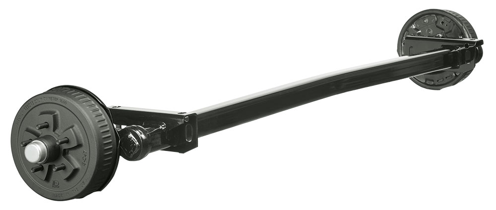
A torsion axle is designed as a completely self-contained axle and suspension system. The trailing arm-type torsion axle uses complex natural rubber cords that support heat-treated inner bars of solid steel. The rubber cords are compressed around the inner bars and the steel torsion arm or spindle assemblies.
These arms can be specified to a range of starting angles, which allows the designer to tailor the running height of the vehicle. Dexter provides options to meet the needs of many trailer and vehicle applications.
Understanding Axles
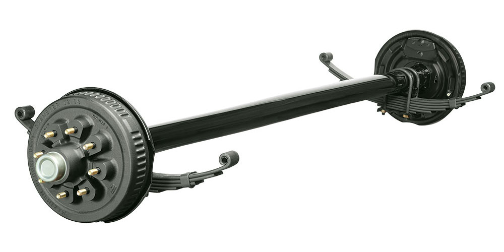
Leaf spring axles use steel spindles welded to tubing to form an axle beam. Depending on the capacity rating of the axle, spindles are usually available in either a straight or drop design to help designers establish the desired frame height or ground clearance.
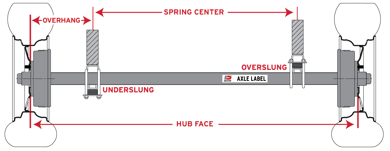
Leaf springs are attached to the axle using U-bolts and can be positioned either under or over the tube. Use under-mounted springs, also called underslung, to lower the frame height. Use over-mounted springs, also called overslung, to raise the frame. The designer can choose stamped steel hangers of varying heights to allow additional control of vehicle height.
Selecting Axles and Running Gear
The following questions are a practical starting point when selecting axles and running gear for a trailer or vehicle application.
Determine the Gross Vehicle Weight, or GVW, by calculating the weight of the empty trailer plus the weight of the intended cargo. For example, a 2,000 lb empty trailer carrying 8,000 lb of cargo has a 10,000 lb GVW.
After determining GVW, determine the Gross Axle Weight, or GAW, which is the percentage of weight carried by the axles. Divide the GAW by the number of axles. For example, 10,000 lb GAW on tandem axles requires a minimum of 5,000 lb capacity per axle.
Most states require brakes at certain trailer capacities, commonly 3,000 lb or more. Confirm local requirements and choose the brake type: electric, electric self-adjust, hydraulic uni-servo, hydraulic free-backing, hydraulic duo-servo, hydraulic disc, or air brakes.
The bolt pattern can vary by axle capacity. It also determines the type of tire and wheel that can be used.
The most common industry measurement is hub face. Hub face is measured from the wheel mounting surface on one hub to the wheel mounting surface of the opposite hub.
Spindle type: Straight spindles are used mostly when the bed is over the tires or when low deck height is not required. Drop spindles are flat beds, utility trailers, and other designs where the lowest possible ground clearance is desired.
Spring centers: Spring centers are the centerline measurement of the spring mounting pads. Spring centers are usually matched to the approximate frame width of the trailer.
Spring type: Double-eye or slipper springs may be selected. Double-eye springs are used with shackle-type suspensions. Slipper springs are heavier-duty springs used with slipper-type suspensions. U-bolt kits can be ordered with axles.
Hanger kit: Common hanger kits include single, tandem, or triple sets for both double-eye and slipper springs. Hanger kits include spring hangers and necessary mounting hardware.
Outside frame dimension: Because torsion axles mount directly to the frame, it is necessary to know the outside frame measurement in order to install the axle correctly. This is also called bracket measurement.
Starting angle: The starting angle is the position of the spindle in reference to the trailer frame. To make it simpler to choose the correct starting angle, consult the appropriate torsion axle tables for the axle type.
Axle Measurements
When determining axle dimensions, the following information is important. Use the correct measurement method for the axle style being ordered.
Tip: Always reference the appropriate chart illustrations to ensure correct measurement of spring brackets, hub face, overhang, and starting angle.
Leaf spring assemblies may be overslung or underslung. Over- or under-slung positioning affects trailer frame height and should be considered with hanger style, spring type, and desired ride height.
Torflex brackets and start angles are part of the axle design. Confirm hub face, outside bracket dimension, and starting angle before ordering.
Reference Guide
Use this glossary to understand common axle assembly terms used during selection, ordering, and measurement.
Spring Axle: Identified by leaf springs attached to the axle tube.
Torsion Axle: Identified by the torsion spindle arm attaching the hub to the axle beam. These axles do not use a spring for suspension and are attached directly to the frame using brackets.
Beam: Axle tube with a spindle at each end.
Idler Axle: An axle with hubs that do not include a drum and do not include brakes.
Capacity: How much weight the axle can support without damage. This is determined by Gross Vehicle Weight and Gross Axle Weight.
Hub Face: Length of the axle measured from the base of one wheel stud to the base of the wheel stud on the opposite end of the axle.
Bolt Pattern: Number of bolt holes and measurement of the bolt circle.
Spring Center: Distance from the center of one spring to the center of the opposite spring.
Outside of Bracket: Measurement from the outer edge of one mounting bracket to the outer edge of the opposite mounting bracket.
Start Angle: Position of the spindle arm in reference to the trailer frame.
Torsion Spindle Arm: The component on a torsion axle where the wheel hub is mounted.
Camber: Axles are typically built with a bend in the tube to compensate for expected deflection under trailer load.
Spindle: End section of an axle onto which hubs are fitted. The spindle may be straight or drop.
Double Eye Spring: Leaf spring with one eye on each end of the spring.
Slipper Spring: Leaf spring with one eye on one end while the other end is flat and slides into a hanger.
Underslung: Axle springs are mounted below the axle.
Overslung: Axle springs are mounted above the axle.
Top Mount: Mounting brackets on a torsion axle attached to the top of the axle tube.
Side Mount: Mounting brackets on a torsion axle attached to the side of the axle tube.
Bracket Orientation: Position that brackets are manufactured onto the torsion axle by the factory.
Standard Orientation: Longest vertical length of the bracket is facing toward the center of the axle.
Reverse Orientation: Longest vertical length of the bracket is facing toward the outboard end of the axle.
Bracket Profile: Height that the brackets are manufactured onto the axle tube by the factory.
Standard Profile Bracket: Base of the mounting bracket is manufactured flush against the top of the axle tube.
High Profile Bracket: Base of the mounting bracket is manufactured 1 inch or 3 inches above the top of the axle tube.
Overhang: Difference between hub face and spring center or outside bracket measurement. It affects stress and clearance.
Track Width: Distance from the center of the dual wheel on one side to the center of the dual wheel on the opposite side.
Brake Flange: Plate mounted to the spindle or axle where the brake assembly bolts to the axle.
Derate: Capacity may be diminished if an axle is built to exceed recommended dimensions.
How to Measure
This chart is a handy guide for figuring the hub face dimensions when only an axle beam with a flange is available to measure.
Note: These equations apply only to axles where the same hub is used. For example, any hub face axle using a 3,500 lb axle has a total flange-to-hub face difference of 6.34 inches, whether it is straight, drop, or Torflex.
Torflex Reference
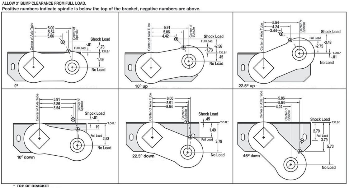
Dimensions shown in torsion articulation charts are examples only. Always refer to the specific torsion axle page for correct dimensions. The process below explains how the dimensions are interpreted.
Use the starting-angle illustration to determine the distance from the center of the spindle to the top of the bracket at no load. Dexter recommends that fenders should be located approximately 5.3 inches above the no-load position.
Shock load is calculated as the difference between full load and shock load positions. In the example shown, full load moves to shock load by .92 inches.
Some starting angles move the spindle arm forward as the axle moves through load positions. The example notes a forward movement of .94 inches between no load and full load.
When trailing arm starts at 22.5 degrees down or 45 degrees down, calculations are subtractions rather than additions. In one example, travel from no load to full load is 3.79 inches, travel from full load to shock load is .45 inches, and the total becomes 3.34 inches.
Allowable bump clearance from full load: positive numbers indicate a spindle is below the top of the bracket; negative numbers are above.
